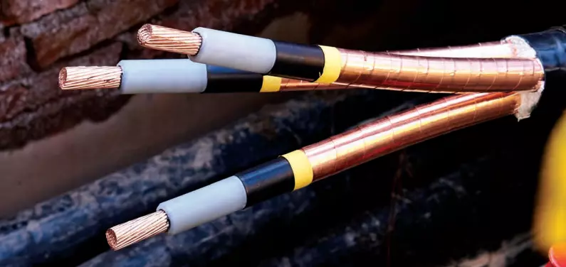
Power and Data Cable Monitoring
The Problem
Underground Infrastructure; once installed needs to stand the test of
time. In some cases, data cables, wires, and power transmission
lines can be expected to have an operating life from a few decades up to almost a
century without the possibility of a visual
inspection.
Monitoring for wear, damage, or corrosion of the cable is extremely difficult and
often power failure or data outage is the first sign of
a problem.
Often, these assets are installed in areas that have multiple uses by various stakeholders and in the event of a failure or damage
can be logistically difficult and expensive to access for repair.
Due to their accessibility when compared to overhead lines, it should also be noted
that third-party intrusion (both accidental
and nefarious) is a much greater threat to buried power transmission lines.
Subsequently the risk of exposure to Arc Flash from live
conductors and the potential for electric shock or electrocution are much greater. As
well as the possibility for optical cables to be
damaged leading to extended telecommunication outages.
Additionally performance of these cables is constantly degrading over time due to
material and environmental factors. This effect
although slow and unpredictable is inevitable and ultimately causes failure of the
conductor on the optic. The location of these faults is a
major challenge and a significant contributor to downtime.
Ultimately to manage these risks a method of around-the-clock monitoring is required
that can be fitted during construction or
retrofitted to existing infrastructure. Due to the long runs transmission cables
need to cover, traditional instrumentation must be installed at regular intervals along the cable run and require supporting
infrastructure (power and communications) to each
device, an entirely impractical proposal.
The Solution
To solve this problem a solution would need to do the following:
- Detect issues as a distributed sensor rather than a point sensor
- Require no additional field infrastructure such as power or communications
- Operate in real time
- Low cost per meter
- Autonomous detection with low false alarm rate
- Autonomous detection with low false alarm rate
Principle of Operation
The Praetorian system interrogator unit is connected to one end of a fiber optic cable which is attached to or buried with the cable or infrastructure being monitored. The interrogator produces rapidly pulsed laser light set at a precise frequency that excites the fiber and causes it to be responsive to physical changes around it. Some of this light is reflected back (backscattered) to the light source where the interrogator records and analyses looking for changes to its color relating to physical effects in the application.
Functionality of Power and Data Cable Monitoring
Praetorian Fiber Optic Sensing (FOS) uses a combination of Distributed Acoustic Sensing
(DAS) and Distributed Temperature
Sensing (DTS) to protect underground buried assets. By exciting a fiber optic core
within a cable the Praetorian Interrogator is able to
utilize the fibers as a distributed network equivalent to up to 1.6 Million individual
vibration, temperature, and strain sensors.
Because a praetorian utilizes a number of different sensing methods it is possible to
observe events in a number of physically
independent ways, consequently Praetorian is inherently resistant to taking a given
reading and giving a false alarm due to the
requirement for multiple physical effects to simultaneously occur at the same location
to signify an event and trigger an alarm.
Through a combination of distributed vibration, temperature and strain monitoring it is possible to determine multitudes of different physical events along a cable, including but not limited to:
- Detection of partial discharge
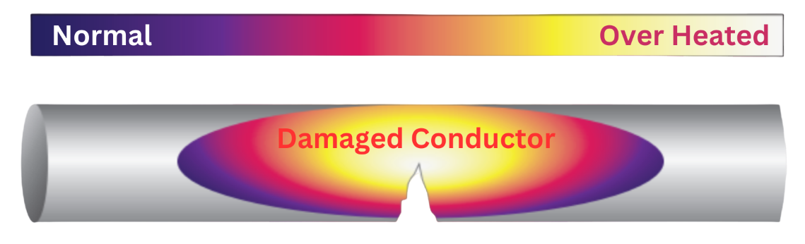
- Detection of hot spots
- Early alert of third party intrusion (accidental or nefarious)
- Conductor break detection
- Ground condition assessment
- Prevention arc flash events from conductor contact
- Detection of optical loss
- Detection of fiber break
- Detection of pit or trench lid being opened
- Determination of network operational status (thermal loading)
The key inputs to the RTTR cable rating modeling are required as follows:
- Cable size and type, installation configuration (cable laying formation)
- Soil ambient temperature
- Real time loading
- Soil thermal resistivity and cable backfill material thermal resistivity if used
The outputs from a RTTR used in a buried cable environment include:
- Real time conductor temperature along the power cable
- Transient calculations for Time/ Current/Temperature
- Emergency ratings – this can be for a range of times from typically 30 minutes to 48 hours+
Heat Image Under The Thermal Detection
Temperature Monitoring: Temperature Profiling
The use of distributed temperature monitoring for ground temperature monitoring is a common supplementary use of fiber optic sensing DTS systems. Benefits include:
- Monitoring of annual and seasonal changes in ground condition
- Ground freezing and flood monitoring
- Ground water table interaction
- Ground temperature monitoring for material degradation monitoring.
Live Optical Condition Monitoring
By analyzing the resultant return signal from Praetorians Distributed Acoustic Sensing (DAS) light pulse a number of optical fault conditions can be detected due to the presence of a loss of return light. Time of flight is used to determine the location of that loss where it occurs. Different optical loss conditions can be detected including (but not limited to):
- Micro-bends
- Macro-bends
- Connector losses
- Fusion splice losses
- Impurities
- Fiber cut
- Time based degradation.
- Moisture and hydrogen infusion loss.
Advantages of Power and Data Cable Monitoring
- Praetorian can function where the cable cannot be visually inspected (due to burial)
- Fiber Optic Sensing detects not only the presence of the fault of failure but its specific location
- Praetorian is extremely sensitive, detecting sounds well below frequency human hearing can manage
- Due to the use of “long haul” single mode fiber Praetorian is able to detect faults over long hauls
- Existing fiber optic data infrastructure may be utilized
- System is passive, no electricity is required in the field
- No maintenance or calibration require after commissioning
- Self diagnostics monitor the unit’s condition and maintain optimum performance
- Not effected by electromagnetic fields (EMF), lightning or weather events
- Easy, low cost installation with cable fingertips
- Low cost per meter